What is Cross Slope (Camber) in Road Design?
In highway engineering, cross slope — commonly called camber — is the intentional transverse gradient given to a road surface perpendicular to its centreline. Unlike the longitudinal gradient that controls how steep a road climbs or descends, cross slope works in the width-wise direction to ensure that rainwater drains quickly off the pavement surface rather than pooling on it.
A road without adequate cross slope quickly accumulates surface water during rain, reducing tyre-road friction (skid resistance), weakening the sub-grade through water infiltration, and creating aquaplaning hazards for drivers. Proper camber is therefore one of the most fundamental requirements in cross-sectional design of any highway.
Why is Camber Provided? Key Objectives
- Surface Water Drainage: Quickly removes rain water from the road surface toward side drains or shoulders.
- Pavement Protection: Particularly critical for gravel and bituminous surfaces prone to erosion from standing water.
- Sub-grade Integrity: Prevents moisture ingress into pavement layers, maintaining structural strength.
- Improved Skid Resistance: A dry road surface offers significantly better tyre grip than a wet one.
- Quick Drying: Faster drying after rain reduces the duration of hazardous wet-road conditions.
Types of Camber — Shapes Explained
1. Parabolic Camber
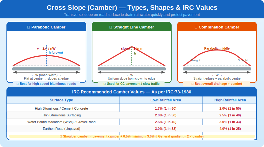
The parabolic camber follows the mathematical equation y = 2x²/nW. In this shape, the road surface is nearly flat near the centre crown and the slope increases progressively toward the edges. This gradual change in cross-slope makes the transition smooth for high-speed vehicle tyres, providing a comfortable ride without sudden lateral shock.
It is the preferred type for bituminous and asphalt pavements carrying fast-moving traffic. The mathematical derivation comes from setting the crown height y₀ = W/2n at the edge (x = W/2), which gives the constant a = 2/nW in the parabola y = ax².
2. Straight Line Camber
Here, the road surface slopes uniformly from the crown to the edge at a constant gradient of 1 in n. The cross-section forms a simple inverted V-shape (or A-shape when viewed end-on). While easy to set out and construct, it creates an abrupt change of direction at the crown, causing vertical impact on vehicle suspensions at higher speeds.
This type is suitable for cement concrete pavements and low-speed roads where construction simplicity is prioritised over riding comfort.
3. Combination Camber
As the name suggests, this is a blend: the central portion uses a parabolic curve for ride comfort, while the outer portions use straight lines for easier construction. It balances the advantages of both types — smooth riding near the centre and simple construction at the edges. This is common on higher-category roads with mixed traffic.
Parabolic Camber Formula Derivation
Consider a road of total width W. For a parabolic camber profile y = ax²:
- At the edge: x = W/2 and y = y₀ (crown height above edge level)
- Camber value: 1/n = y₀ / (W/2) → y₀ = W/2n
- Substituting: W/2n = a(W/2)² → a = 2/nW
- ∴ y = 2x²/nW (General parabolic camber equation)
Crown height above edges: h = W/(2n) or equivalently: tan θ = 1/n = h/(W/2)
IRC Recommended Camber Values
| Pavement Surface Type | Low Rainfall Area | High Rainfall Area |
|---|---|---|
| High Bituminous Surfacing / Cement Concrete | 1.7% (1 in 60) | 2.0% (1 in 50) |
| Thin Bituminous Surfacing | 2.0% (1 in 50) | 2.5% (1 in 40) |
| Water Bound Macadam (WBM) / Gravel | 2.5% (1 in 40) | 3.0% (1 in 33) |
| Earthen / Unpaved Road | 3.0% (1 in 33) | 4.0% (1 in 25) |
Key principle: Smoother, less permeable surfaces (like concrete) need less camber because water runs off easily. Rougher or more porous surfaces (like gravel or earth) need steeper camber to overcome surface resistance and ensure drainage.
Special Notes from IRC
- Shoulder camber must be kept 0.5% steeper than the pavement camber, with a minimum of 3.0%, so water does not flow from shoulder onto the carriageway.
- The longitudinal gradient of a road is generally twice the camber value — ensuring that combined drainage works effectively.
- On super-elevated sections, the shoulder must match the carriageway crossfall to avoid water pooling at the joint.
- Excessively steep camber is undesirable — it causes surface erosion, vehicle discomfort, and difficulty in maintaining lane position on curves.
Camber on Divided vs Undivided Highways
On an undivided (single carriageway) highway without a median, the road surface rises to a crown at the centreline and slopes symmetrically toward both edges — the classic “hump” profile. On a divided (dual carriageway) highway, each carriageway is given a unidirectional slope toward its respective outer edge, since the median prevents water from draining inward.
Solved Example — Crown Height Calculation
Problem: A major district road of WBM pavement is 3.8 m wide in a heavy rainfall area. Find the height of crown with respect to edges.
Solution:
For WBM road in high rainfall: camber = 1 in 33
h = (W/2) × (1/n) = (3.8/2) × (1/33) = 1.9/33 = 0.0576 m ≈ 0.058 m
For a 7.0 m wide bituminous concrete state highway: camber = 1 in 50 (high rainfall)
h = (7.0/2) × (1/50) = 3.5/50 = 0.07 m = 7 cm
Revision Summary
- Cross slope (camber) = transverse gradient for surface drainage
- Three types: Parabolic (fast traffic/bituminous), Straight Line (CC/slow roads), Combination (mixed)
- Formula: y = 2x²/nW (parabolic); Crown height h = W/2n
- Higher rainfall → steeper camber | Smoother surface → flatter camber
- Shoulder camber ≥ road camber + 0.5% (minimum 3%)