Home ›
Highway Engineering ›
Geometric Design of Highway
Geometric Design of Highway as per Indian Standard (IRC)
Topics covered: Design speed • Sight distance • Horizontal curves • Superelevation • Widening • Gradient • Vertical curves • Cross-section elements • All IRC values • GATE & SSC JE FAQs with diagrams
- What is Geometric Design of Highway?
- Design Speed as per IRC
- Cross-Section Elements (Diagram 1)
- Sight Distance — SSD, ISD, OSD, HSD (Diagram 2)
- Horizontal Alignment and Curves
- Superelevation / Banking (Diagram 3)
- Extra Widening on Curves
- Gradient (Diagram 4)
- Vertical Curves — Summit and Valley (Diagram 5)
- IRC Quick Reference Table
- Keywords / Glossary
- FAQs for GATE & SSC JE
1. What is Geometric Design of Highway?
Geometric design of a highway means designing the visible and physical shape of a road — how wide it is, how it curves left and right, how steep it goes up and down, and how far a driver can see ahead. If the geometry is wrong, accidents happen. If it is right, vehicles travel safely and comfortably at the intended speed.
In India, all geometric design rules are given by the Indian Roads Congress (IRC):
- 📘 IRC: 38-1988 — Horizontal curves (superelevation, transition curves, extra widening)
- 📘 IRC: 52-2001 — Vertical curves (summit and valley curves)
- 📘 IRC: 73-1980 — Geometric design standards for rural highways
- 📘 IRC: 86-1983 — Geometric design standards for urban roads
2. Design Speed as per IRC
Design speed is the maximum safe speed for which all geometric elements of a road are designed. Every calculation — curve radius, sight distance, superelevation — depends on this speed. A higher design speed means wider curves, longer sight distances, and flatter gradients.
| Road Type | Terrain | Ruling Speed (km/h) | Minimum Speed (km/h) | Absolute Min (km/h) |
|---|---|---|---|---|
| National Highway (NH) | Plain | 100 | 80 | 60 |
| NH | Rolling | 80 | 65 | 50 |
| NH | Hilly | 50 | 40 | 30 |
| NH | Steep | 40 | 30 | 20 |
| State Highway (SH) | Plain | 80 | 65 | 50 |
| SH | Rolling | 65 | 50 | 40 |
| Major District Road | Plain | 65 | 50 | 40 |
| MDR | Rolling | 50 | 40 | 30 |
| Village Road / ODR | Plain | 40 | 30 | 20 |
3. Cross-Section Elements
A cross-section is what you see when you cut the road at right angles and look at it from the front — like a slice. It shows every part of the road width from boundary to boundary.
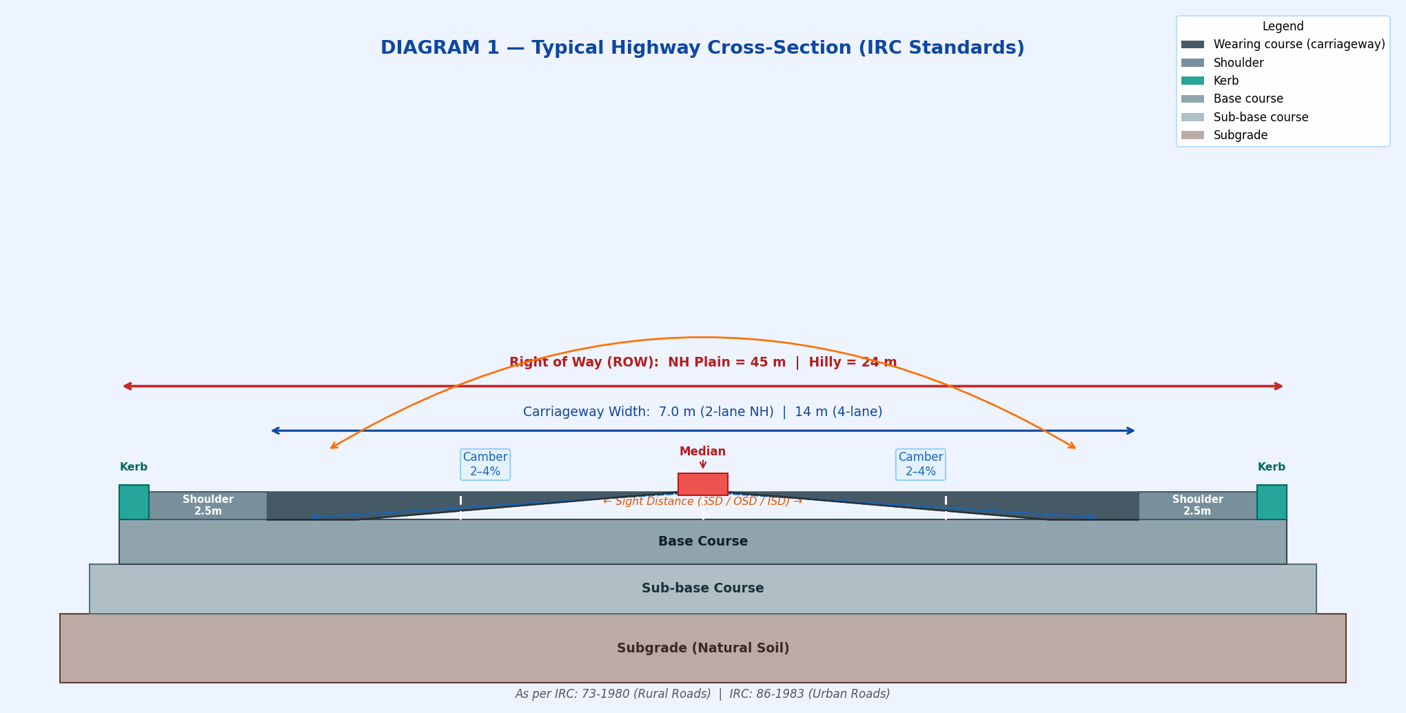
Fig 1: Typical two-lane highway cross-section showing all elements as per IRC: 73-1980
3.1 Carriageway Width (IRC: 73)
| Road Type | Number of Lanes | Carriageway Width |
|---|---|---|
| Single lane rural road | 1 | 3.75 m |
| Intermediate lane | 1.5 (shared) | 5.5 m |
| Two-lane road (NH/SH) | 2 | 7.0 m |
| Four-lane undivided | 4 | 14.0 m |
| Six-lane divided | 6 | 21.0 m |
3.2 Camber (Cross Slope)
Camber is the transverse slope given to the road surface so rainwater drains off quickly to the sides. The road is highest at the centre and slopes down on both sides — this shape is called a crown.
| Surface Type | Recommended Camber | Range |
|---|---|---|
| CC / High bituminous surface | 2% | 1.7% to 2.5% |
| Thin bituminous surface | 2.5% | 2% to 3% |
| Gravel / WBM surface | 3% | 2.5% to 3.5% |
| Earth road | 4% | 3.5% to 5% |
3.3 Shoulder Width
- NH/SH paved shoulder (plain): 2.5 m
- Rural roads shoulder: 1.0 to 1.5 m
- Shoulder slope: 3–5% (steeper than carriageway camber)
3.4 Right of Way (ROW)
ROW is the total land width acquired for the road. No private construction is allowed inside ROW.
| Road Type | ROW — Plain / Rolling (m) | ROW — Hilly (m) |
|---|---|---|
| NH / SH | 45 m | 24 m |
| MDR | 25 m | 18 m |
| ODR | 15 m | 12 m |
| Village Road | 12 m | 9 m |
4. Sight Distance
Sight distance is the length of road ahead that a driver can clearly see from their seat. It must be long enough for the driver to stop safely or safely complete an overtaking manoeuvre without any collision risk.
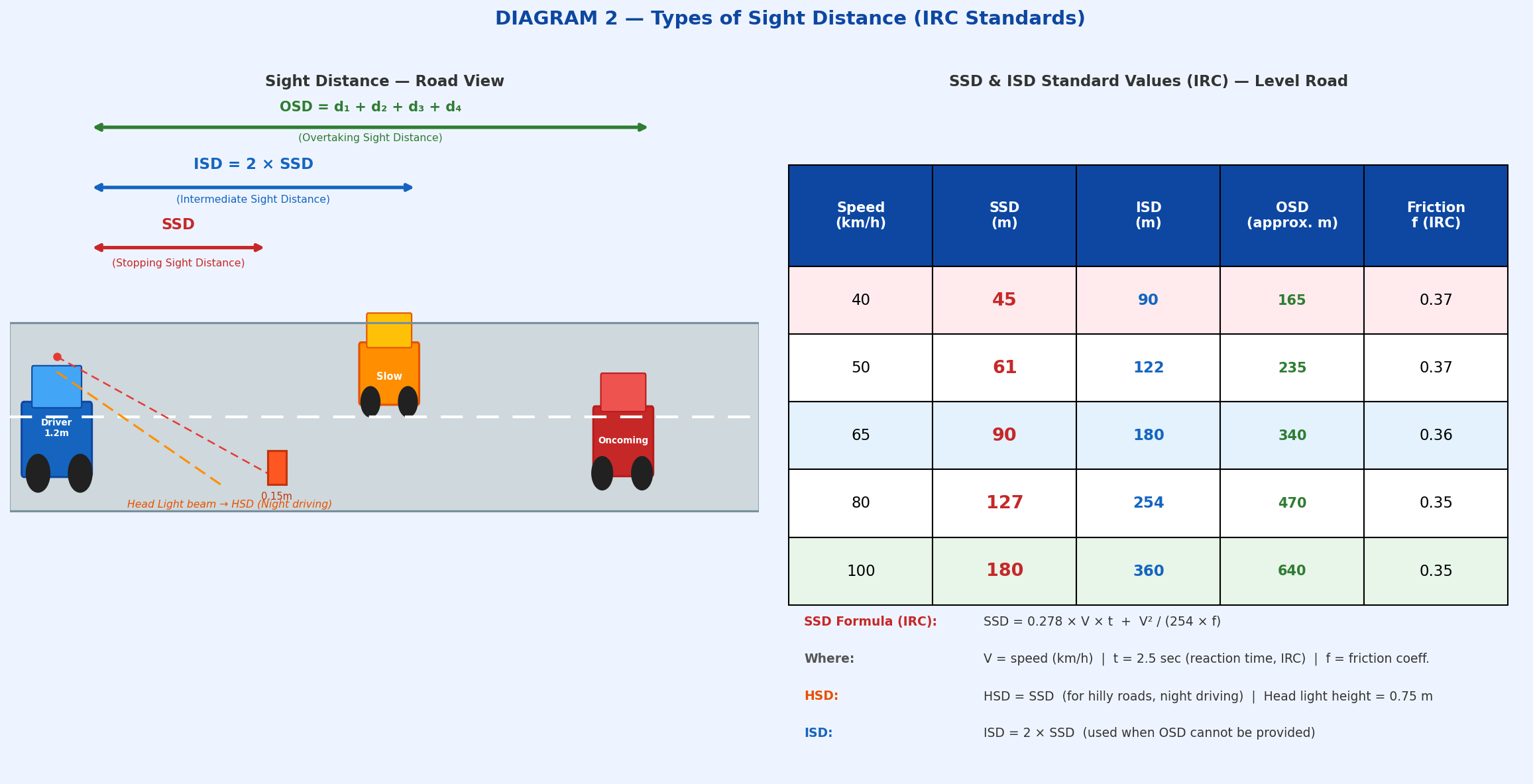
Fig 2: Types of sight distance — SSD, ISD, OSD shown on road with IRC standard values table
4.1 Stopping Sight Distance (SSD)
The minimum distance within which a driver must stop safely when an obstacle suddenly appears on the road. SSD governs summit curve design.
V = speed (km/h) | t = 2.5 sec (IRC reaction time) | f = friction (0.35–0.37)
4.2 Intermediate Sight Distance (ISD)
ISD = 2 × SSD. Used on roads where full OSD cannot be provided but SSD alone is not enough. Allows a driver to abort an overtaking manoeuvre safely on seeing an oncoming vehicle.
4.3 Overtaking Sight Distance (OSD)
Distance needed to safely overtake a slow vehicle. This is the largest of all sight distances.
OSD = d₁ + d₂ + d₃ + d₄ (two-way road)
d₁ = distance during reaction time | d₂ = overtaking distance | d₃ = safety clearance | d₄ = oncoming vehicle distance
4.4 Head Light Sight Distance (HSD)
Distance illuminated by vehicle headlights during night driving. HSD governs valley curve design.
- Head light height above road: 0.75 m
- Beam inclination: 1 degree
- For hilly roads: HSD = SSD
| Speed (km/h) | SSD (m) | ISD (m) | OSD approx (m) | Friction f |
|---|---|---|---|---|
| 40 | 45 | 90 | 165 | 0.37 |
| 50 | 61 | 122 | 235 | 0.37 |
| 65 | 90 | 180 | 340 | 0.36 |
| 80 | 127 | 254 | 470 | 0.35 |
| 100 | 180 | 360 | 640 | 0.35 |
5. Horizontal Alignment and Curves
When a road changes direction horizontally (turns left or right), a horizontal curve is provided. The most critical design value is the minimum radius, below which the road becomes unsafe.
Types of Horizontal Curves
- Simple circular curve — Constant radius, most common
- Compound curve — Two simple curves of different radii on same side
- Reverse curve — Two curves of opposite direction (S-shape) — not recommended by IRC
- Transition curve (Spiral) — Gradually changing radius; IRC recommends Euler’s Spiral (Clothoid)
V = speed (km/h) | e = max superelevation (decimal) | f = 0.15 (lateral friction, IRC)
| Speed (km/h) | Min Radius (m) at e=7%, f=0.15 | Road Type |
|---|---|---|
| 40 | 45 m | Village Road |
| 50 | 90 m | ODR |
| 65 | 155 m | MDR |
| 80 | 230 m | State Highway |
| 100 | 360 m | National Highway |
6. Superelevation (Banking on Curves)
When a vehicle goes around a curve, centrifugal force pushes it outward. Superelevation tilts the entire road surface inward (toward the centre of the curve) to counteract this force and prevent vehicles from skidding outward.
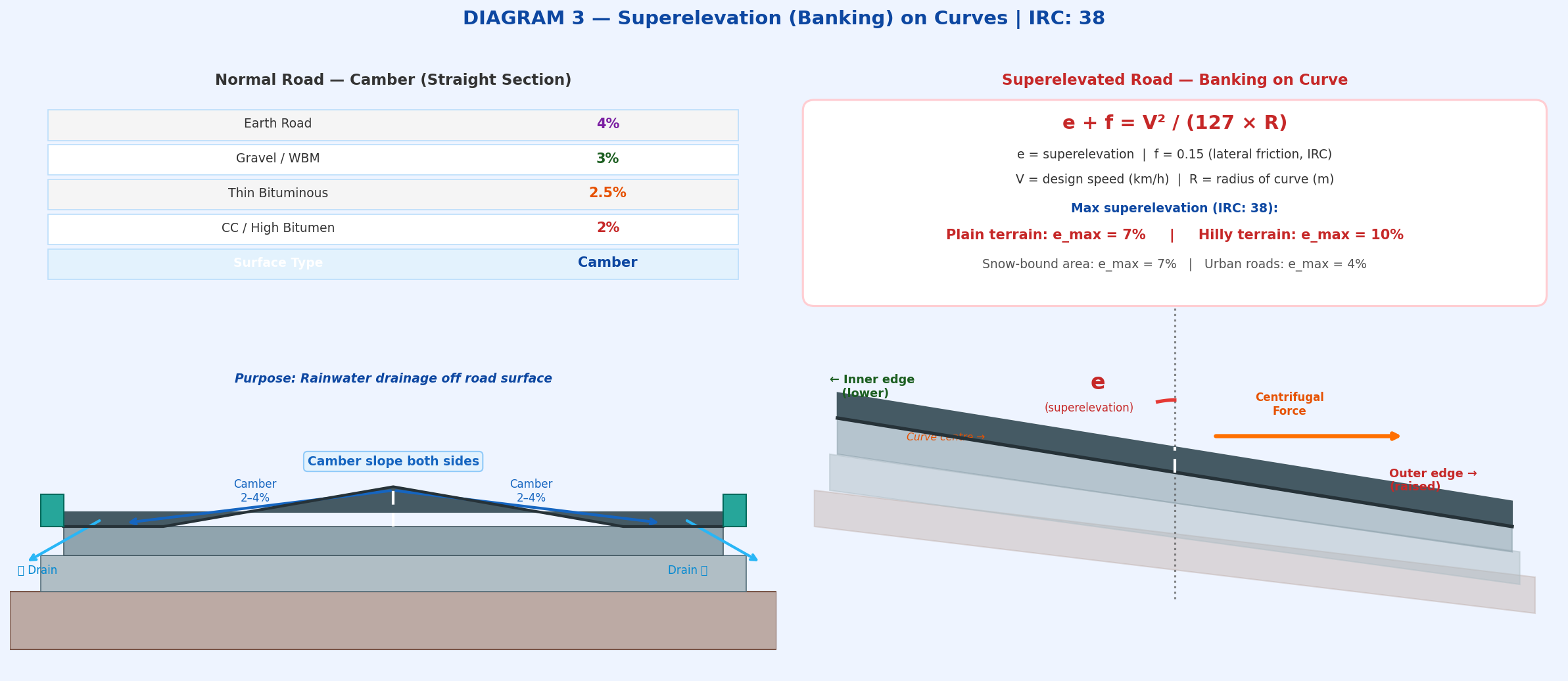
Fig 3: Left — Normal road camber for drainage. Right — Superelevated road on curve to counteract centrifugal force (IRC: 38)
e = superelevation (decimal) | f = 0.15 (lateral friction, IRC) | V = speed (km/h) | R = radius (m)
Maximum Superelevation Values (IRC: 38)
- Plain and rolling terrain: emax = 7%
- Hilly roads (no snow): emax = 10%
- Snow-bound roads: emax = 7%
- Urban roads: emax = 4%
- Lateral friction coefficient: f = 0.15 (IRC design value)
7. Extra Widening on Curves
On curves, the rear wheels track inside the front wheel path and drivers psychologically tend to use more road width. So extra width is added to all lanes at curves.
Wm (mechanical widening) = nℓ² / (2R) — n = number of lanes, ℓ = 6 m (standard wheelbase), R = radius (m)
Wp (psychological widening) = V / (9.5 × √R) — V = speed (km/h)
8. Gradient (Vertical Alignment)
The slope of the road in the vertical direction is called the gradient, expressed as percentage (%) or as a ratio (1 in n). A positive gradient means the road rises; negative means it falls.
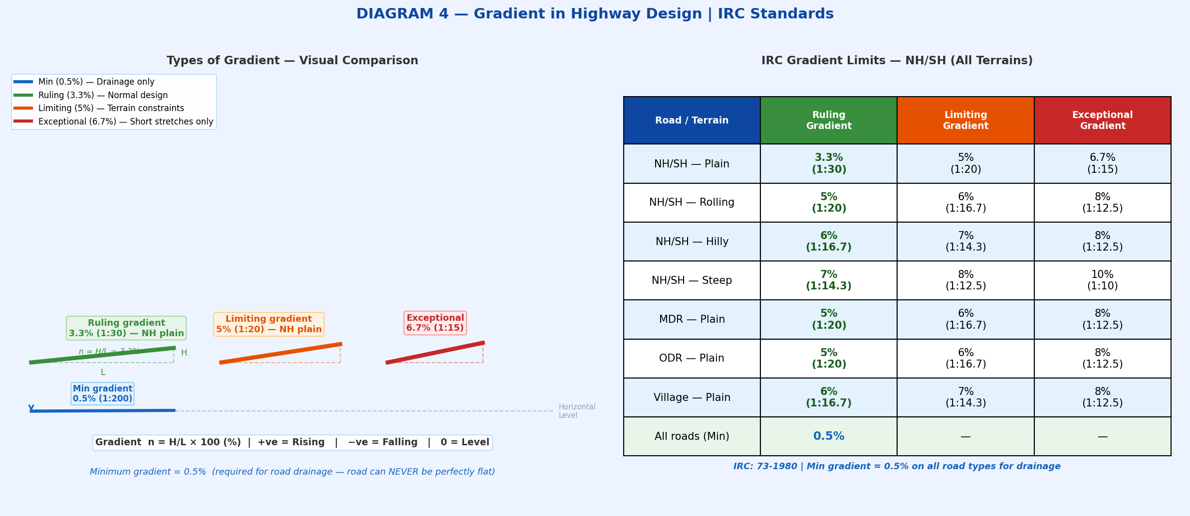
Fig 4: Visual comparison of gradient types — ruling, limiting, exceptional and minimum (0.5%) as per IRC: 73
Types of Gradient (IRC)
- Ruling gradient — Standard gradient used for design. Should always be aimed for.
- Limiting gradient — Steeper than ruling; used when terrain makes ruling grade impossible.
- Exceptional gradient — Steepest allowed; only for very short stretches in extreme terrain.
- Minimum gradient — 0.5% on ALL roads. Required so water drains off the road. Road must NEVER be 0% flat.
| Road / Terrain | Ruling Gradient | Limiting Gradient | Exceptional Gradient |
|---|---|---|---|
| NH/SH — Plain | 3.3% (1 in 30) | 5% (1 in 20) | 6.7% (1 in 15) |
| NH/SH — Rolling | 5% (1 in 20) | 6% (1 in 16.7) | 8% (1 in 12.5) |
| NH/SH — Hilly | 6% (1 in 16.7) | 7% (1 in 14.3) | 8% (1 in 12.5) |
| NH/SH — Steep | 7% (1 in 14.3) | 8% (1 in 12.5) | 10% (1 in 10) |
| All roads (Minimum) | 0.5% | — | — |
9. Vertical Curves — Summit and Valley
When two road gradients of different values meet, they are connected by a vertical curve to give a smooth and comfortable ride. Vertical curves are always parabolic (never circular) because a parabola provides a uniform rate of change of gradient.
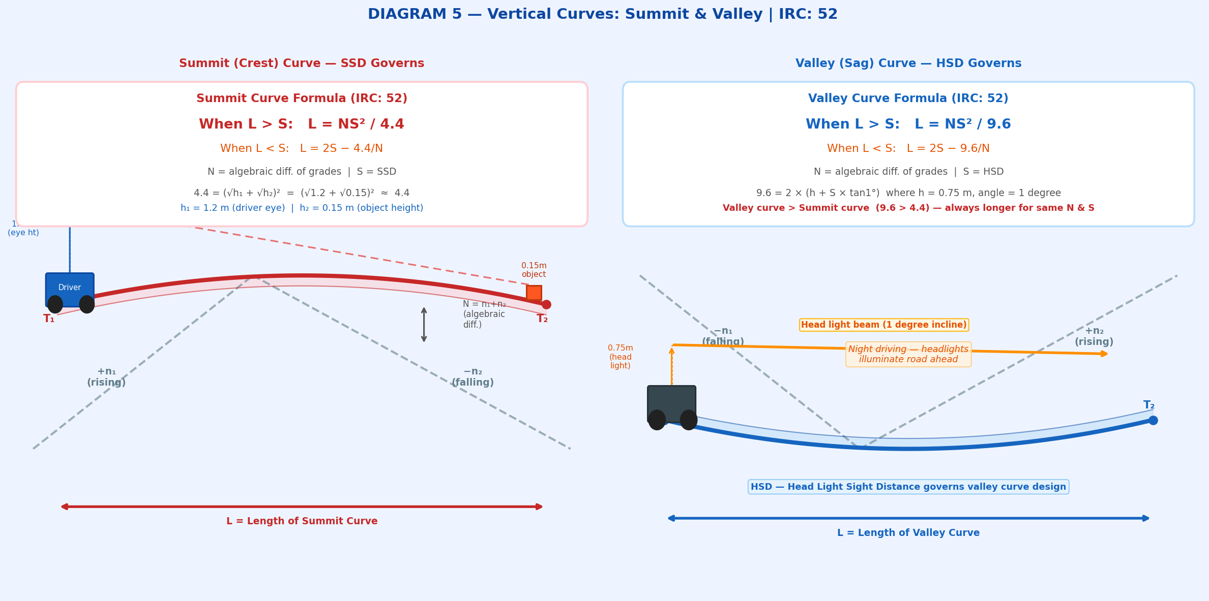
Fig 5: Summit curve (left) governed by SSD and Valley curve (right) governed by HSD as per IRC: 52-2001
9.1 Summit (Crest) Curve — SSD Governs
Formed when a rising gradient meets a falling gradient. Driver cannot see over the top — so stopping sight distance must be available over the crest.
When L < S: L = 2S − 4.4/N
N = algebraic difference of gradients | S = SSD
4.4 = (√h₁ + √h₂)² = (√1.2 + √0.15)² ≈ 4.4
h₁ = 1.2 m (driver eye height) | h₂ = 0.15 m (object height)
9.2 Valley (Sag) Curve — HSD Governs
Formed when a falling gradient meets a rising gradient. During night, the headlight beam must illuminate road far enough ahead to stop safely.
When L < S: L = 2S − 9.6/N
N = algebraic difference of gradients | S = HSD
9.6 = 2(h + S tanα) where h = 0.75 m, α = 1° (head light beam angle)
10. IRC Quick Reference Table
| Parameter | Value (IRC) | IRC Code |
|---|---|---|
| Reaction time | 2.5 seconds | IRC: 66 |
| Lateral friction coefficient (f) | 0.15 | IRC: 38 |
| Max superelevation — plain terrain | 7% | IRC: 38 |
| Max superelevation — hilly terrain | 10% | IRC: 38 |
| Driver eye height | 1.2 m | IRC: 52 |
| Object height (SSD design) | 0.15 m | IRC: 52 |
| Head light height (HSD) | 0.75 m | IRC: 52 |
| Head light beam inclination | 1 degree | IRC: 52 |
| Summit curve constant | 4.4 | IRC: 52 |
| Valley curve constant | 9.6 | IRC: 52 |
| Camber — CC / high bituminous | 2% | IRC: 73 |
| Camber — Earth road | 4% | IRC: 73 |
| Minimum gradient (all roads) | 0.5% | IRC: 73 |
| Wheelbase for widening | 6.0 m | IRC: 38 |
| NH ROW — plain / rolling | 45 m | IRC: 73 |
| NH ROW — hilly | 24 m | IRC: 73 |
| Transition curve type (IRC) | Euler’s Spiral (Clothoid) | IRC: 38 |
11. Keywords / Glossary
Design Speed
Ruling Speed
SSD
OSD
ISD
HSD
Superelevation
Banking
Camber
Carriageway
Right of Way
Shoulder
Transition Curve
Clothoid Euler Spiral
Summit Curve
Valley Curve
Parabolic Curve
Ruling Gradient
Limiting Gradient
Exceptional Gradient
Centrifugal Force
Lateral Friction
Extra Widening
IRC 38
IRC 52
IRC 73
National Highway
Geometric Design of Highway as per Indian Standard
12. FAQs for GATE & SSC JE
🌟 Must-Remember Values — Geometric Design of Highway (GATE & SSC JE)
- Reaction time = 2.5 sec (IRC: 66)
- SSD = 0.278Vt + V²/254f | t = 2.5 s | f = 0.35 to 0.37
- ISD = 2 × SSD • HSD = SSD (hilly roads)
- e + f = V²/127R (superelevation formula)
- Max e = 7% plain | 10% hilly | f = 0.15
- Camber: CC = 2% | Gravel = 3% | Earth = 4%
- Min gradient = 0.5% (never zero!)
- NH plain ruling gradient = 3.3% = 1 in 30
- Summit curve: L = N × S² / 4.4 → SSD governs (h=1.2m, obj=0.15m)
- Valley curve: L = N × S² / 9.6 → HSD governs (HL=0.75m, 1°)
- Valley curve always longer than summit curve for same N and S
- NH ROW plain = 45 m | Hilly = 24 m
- Vertical curves are always parabolic (not circular)
- Transition curve = Euler’s Spiral (Clothoid) — IRC: 38
- NH design speed plain = 100 km/h | SH = 80 km/h
- Two-lane carriageway width = 7.0 m
- Wheelbase for widening = 6.0 m