Building upon foundational surveying principles, Part-2 delves into advanced techniques and critical considerations for achieving precision in diverse field conditions. This segment focuses on intricate aspects of linear and angular measurements, leveling methodologies, and the interpretation of contour maps—all indispensable for complex civil engineering projects. Mastering these detailed concepts ensures accuracy, mitigates errors, and optimizes project execution from planning to construction.
Linear Measurement & Essential Corrections
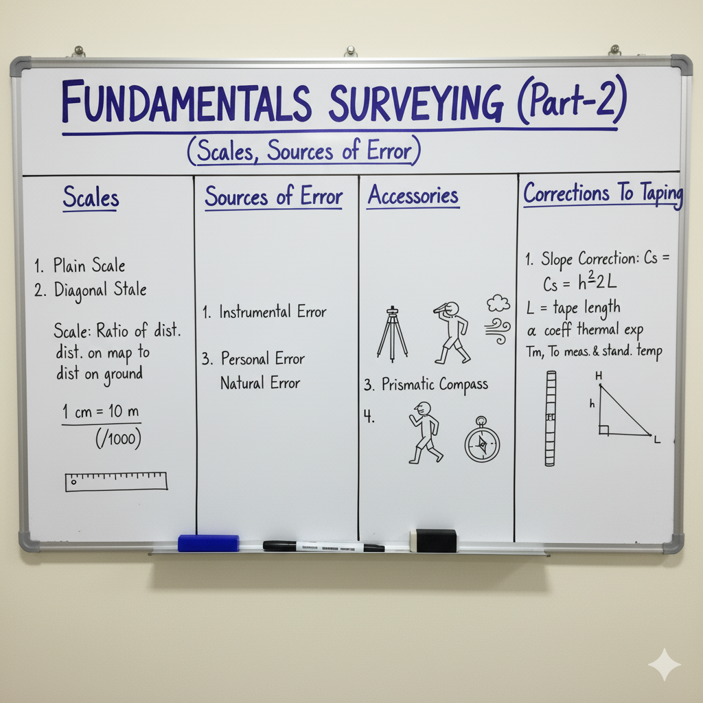
Accurate linear measurements are fundamental to all surveying operations. However, various factors can introduce errors, necessitating specific corrections to measured distances to achieve true values. Understanding these corrections is vital for precision.
| Correction Type | Description | Formula/Concept |
|---|---|---|
| Temperature Correction (Ct) | Applied when the temperature during measurement differs from the standard temperature at which the tape was calibrated. Thermal expansion or contraction affects tape length. | Ct = L α (Tm – To) (L: Measured Length, α: Coeff. of Thermal Expansion, Tm: Meas. Temp, To: Std. Temp) |
| Pull Correction (Cp) | Required when the applied pull (tension) during measurement differs from the standard pull at which the tape was calibrated. Elastic stretch or compression affects tape length. | Cp = (Pm – Po)L / (AE) (Pm: Meas. Pull, Po: Std. Pull, A: Area, E: Modulus of Elasticity) |
| Sag Correction (Cs) | Always negative, applied when the tape sags between supports, forming a catenary. This reduces the horizontal distance being measured. It is dependent on the weight of the tape and tension. | Cs = W2L / (24P2) (W: Total weight of tape between supports, L: Length, P: Pull) |
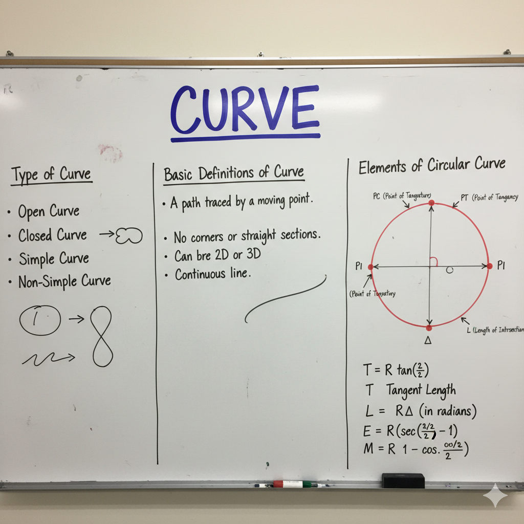
| Slope Correction (Cs) | Always negative, applied when measurements are taken along an inclined surface. The measured slope distance is greater than the true horizontal distance. | Cs = h2 / (2L) or Cs = L(1 – cosθ) (h: Height difference, L: Slope length, θ: Angle of slope) |
Angular Measurement & Bearing Systems
Angular measurements are crucial for establishing directions and positions in surveying. Different bearing systems are used to define the direction of survey lines, with conversions being a key skill. Understanding local attraction is also vital.
| Concept | Definition | Key Characteristics / Conversion |
|---|---|---|
| Bearing | The horizontal angle between a survey line and a fixed reference direction (meridian). The reference can be true, magnetic, or arbitrary. | Used to express direction. ⬆️ |
| Whole Circle Bearing (WCB) | The horizontal angle measured clockwise from the North meridian (0°) to the survey line. Ranges from 0° to 360°. | N➡️E➡️S➡️W➡️N |
| Reduced Bearing (RB) / Quadrantal Bearing (QB) | The acute angle measured from the nearest meridian (North or South) towards the East or West. Ranges from 0° to 90°, always specified with quadrant (e.g., N30°E, S45°W). | N-E, S-E, S-W, N-W Quadrants |
| Fore Bearing (FB) & Back Bearing (BB) | FB is the bearing of a line measured in the direction of progression. BB is the bearing of the same line measured in the opposite direction. | BB = FB ± 180° (+ if FB < 180°, – if FB > 180°) |
| Local Attraction | A disturbance in the magnetic meridian caused by local magnetic influences (e.g., steel structures, electric cables), leading to inaccurate magnetic bearings. | Detected by comparing FB & BB; Corrected by adjusting angles from undisturbed stations. |
Levelling Principles & Methodologies
Levelling is the process of determining relative heights (elevations) of points or objects on the Earth’s surface. It is crucial for designing and constructing elements with specific gradients, drainage, or vertical clearances.
Fundamental Concepts in Levelling
| Concept | Definition | Significance |
|---|---|---|
| Level Surface | A surface perpendicular to the direction of gravity at all points. It is essentially a curved surface parallel to the mean spheroidal surface of the Earth. | Reference for vertical measurements, fundamental for leveling operations. |
| Datum | Any surface or point assumed as a reference for determining elevations. Mean Sea Level (MSL) is the most common and widely accepted datum for large-scale surveys. | Establishes a common vertical reference system for entire regions or countries. |
| Benchmark (BM) | A fixed reference point of known elevation, typically established by government agencies (e.g., Survey of India). It serves as a starting or closing point for levelling operations. | Provides a stable, verifiable elevation for linking local surveys to a national or regional datum. |
| Reduced Level (RL) | The elevation of a point with respect to an assumed or established datum. It represents the vertical distance of a point above or below the datum. | Quantifies the elevation of any point on a map or in the field, crucial for design and construction. |
Common Types of Levelling
| Levelling Type | Description | Primary Use |
|---|---|---|
| Simple Levelling | Determining the difference in elevation between two points visible from a single instrument setup. Uses a single backsight and a single foresight reading. | Small-scale elevation determination, checking relative heights of nearby points. |
| Differential Levelling | Determining the difference in elevation between points that are far apart or not visible from a single setup. Involves multiple setups and ‘turning points’. | Establishing benchmarks, creating long sections for roads/canals, transferring levels over distances. |
| Fly Levelling | A type of differential levelling where only backsight and foresight readings are taken, usually without intermediate readings. Used for rapid determination of approximate levels. | Reconnaissance surveys, quick checks, establishing temporary benchmarks. |
| Profile Levelling | Determining elevations along a specified line (e.g., center line of a road or sewer) at regular intervals or critical points. | Design of roads, railways, sewers, and canals; creating longitudinal sections. |
| Cross-section Levelling | Determining elevations of points on either side of a main survey line, perpendicular to it. Used to establish the configuration of the ground transverse to the main line. | Calculating earthwork volumes for cuts and fills, designing embankments and cuttings. |
Contouring & Applications of Contour Maps
Contouring is the representation of terrain relief on a map using contour lines. A contour line connects points of equal elevation above a datum. Contour maps are invaluable tools for various engineering and planning purposes.
Characteristics of Contour Lines
| Characteristic | Description |
|---|---|
| Closed Loop | Every contour line must close upon itself, either within the map limits or outside them. |
| Never Intersect | Contour lines never intersect each other, except in the rare case of an overhanging cliff or a cave. |
| Uniform Slope | Closely spaced contour lines indicate a steep slope, while widely spaced lines indicate a gentle slope. |
| Ridge & Valley Lines | Contour lines cross ridge lines (watersheds) and valley lines (watercourses) at right angles. Valley lines usually form V-shapes pointing upstream. |
| Highest/Lowest Point | A closed contour line with higher values inside indicates a hill or mountain. A closed contour line with lower values inside indicates a depression or pond. |
Key Uses of Contour Maps
| Application | Benefit of Using Contour Maps |
|---|---|
| Site Selection & Feasibility | Aids in choosing the most suitable site for construction by providing a clear understanding of the terrain, slopes, and drainage patterns. |
| Route Location (Roads, Railways, Canals) | Facilitates the selection of the most economical and efficient alignment for linear projects, minimizing earthwork and optimizing gradients. |
| Earthwork Volume Calculation | Essential for estimating the quantities of cut and fill required for grading, excavation, and embankment construction, directly impacting project costs. |
| Drainage Design | Helps in planning and designing effective drainage systems by visualizing natural water flow paths and identifying areas prone to water accumulation. |
| Reservoir Capacity Estimation | Used to determine the storage capacity of reservoirs by calculating volumes bounded by various contour levels. |
| Military & Strategic Planning | Provides crucial topographical information for military operations, strategic planning, and understanding terrain advantage/disadvantage. |