📋 Table of Contents
🔷 What is Fibre Reinforced Concrete (FRC)?
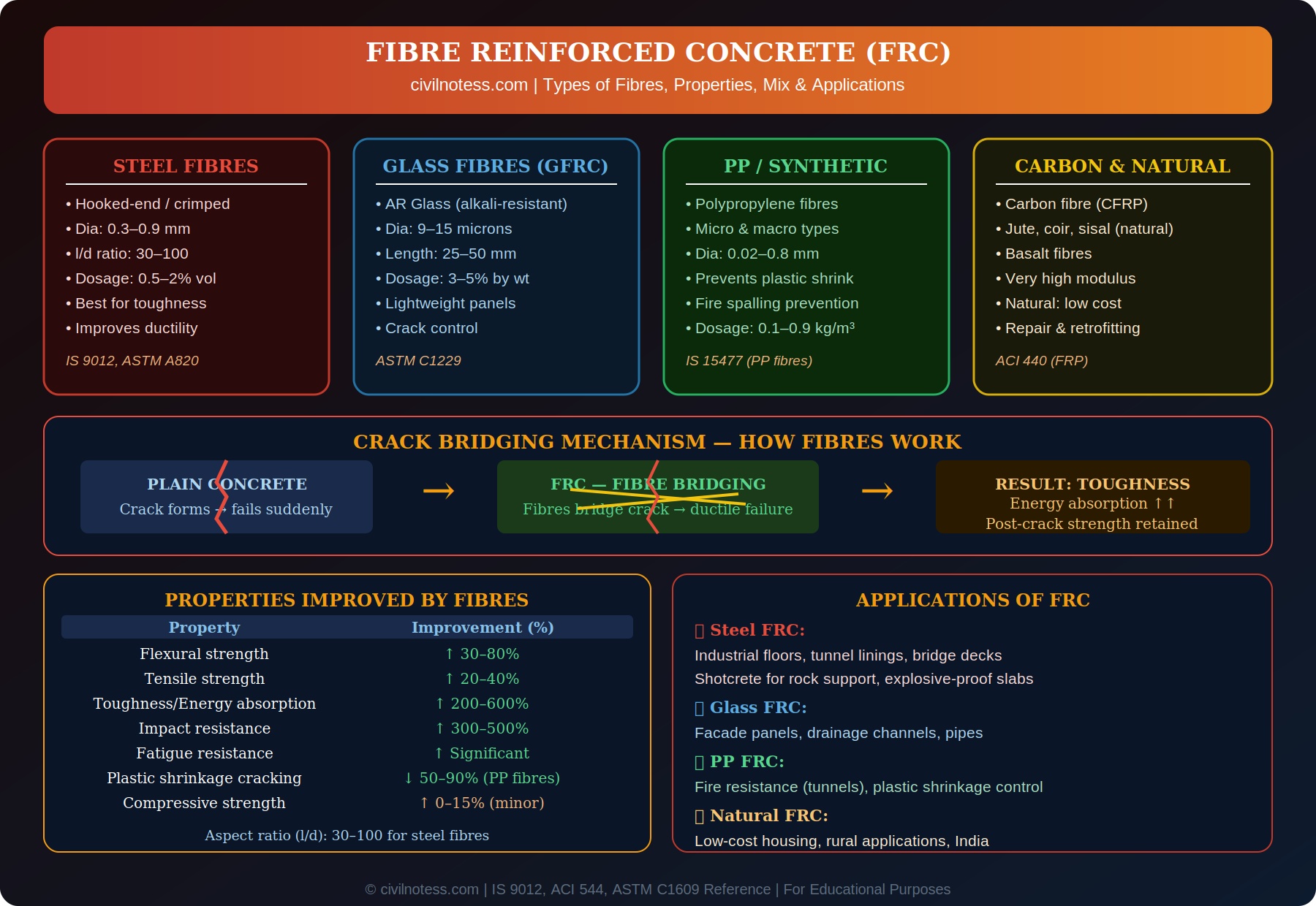
Fibre Reinforced Concrete (FRC) is concrete containing short, discontinuous fibres that are uniformly dispersed and randomly oriented throughout the concrete matrix to improve its mechanical properties — particularly tensile strength, toughness, impact resistance, and crack control.
FRC is defined in ACI 544 and test methods are covered in ASTM C1609 (flexural performance). In India, polypropylene fibres for concrete are covered under IS 15477 and steel fibre shotcrete is used as per IRC SP-91.
1. Bridge cracks and prevent their propagation after first crack
2. Increase toughness (post-crack energy absorption)
3. Improve ductility (change failure from brittle to ductile)
🔩 4 Types of Fibres Used in FRC
1. Steel Fibres
The most widely used structural fibres. Types include:
- Hooked-end steel fibres: Most common. Hooks provide mechanical anchorage in concrete matrix.
- Crimped (undulated) steel fibres: Surface roughness provides bond.
- Paddle/flat-end fibres: Enlarged ends resist pull-out.
- Aspect ratio (l/d): 30–100 (typical). Higher aspect ratio = better performance but harder to mix.
- Fibre diameter: 0.3–0.9 mm | Length: 25–60 mm
- Dosage: 0.5–2% by volume (40–160 kg/m³)
- Standard: IS 9012, ASTM A820
2. Glass Fibres (GFRC — Glass Fibre Reinforced Concrete)
- Must use Alkali-Resistant (AR) glass — ordinary E-glass dissolves in alkaline concrete environment.
- Diameter: 9–15 microns | Length: 25–50 mm
- Dosage: 3–5% by weight
- Primary use: Thin precast architectural panels, drainage channels, pipes.
- Standard: ASTM C1229 / GRCA specifications
3. Polypropylene (PP) / Synthetic Fibres
- Most cost-effective for crack control.
- Micro-PP fibres (0.02–0.06mm dia): Prevent plastic shrinkage cracking; also prevent explosive spalling in fire (melt at ~170°C to create pressure relief channels).
- Macro-PP fibres (0.4–0.8mm dia): Structural performance similar to low-dose steel fibres.
- Dosage: 0.1–0.9 kg/m³ (micro) | 3–10 kg/m³ (macro)
- Standard: IS 15477 (PP fibres for concrete)
4. Carbon Fibres and Natural Fibres
- Carbon fibres: Very high modulus and tensile strength. Used in UHPFRC and repair/retrofitting. Very expensive.
- Basalt fibres: Natural volcanic rock fibre. Good alkali resistance, moderate cost. Growing use in India.
- Natural fibres (Jute, Coir, Sisal): Low cost, available locally. Used for low-cost housing and rural construction in India. Limited durability in cement matrix.
⚙️ Crack Bridging Mechanism — How Fibres Work
Plain concrete is brittle — when a crack initiates and propagates, failure is sudden and catastrophic. Fibres fundamentally change this behaviour:
- Before cracking: Fibres share tensile stress with the cement matrix. First crack strength is slightly improved.
- At cracking: As a crack forms, fibres that span the crack continue to carry load. The crack cannot propagate freely as fibres resist crack opening.
- After cracking (post-crack strength): Fibres are pulled out from the matrix progressively, absorbing large amounts of energy. This gives FRC its characteristic toughness and ductility.
- Multiple micro-cracking: In high-fibre-content FRC, multiple fine cracks form rather than one large crack. This is the basis of UHPFRC (Ultra High Performance FRC).
📊 Properties Improved by Fibres
| Property | Improvement by Fibres | Type of Fibre |
|---|---|---|
| Flexural strength | ↑ 30–80% | Steel, Glass, PP (macro) |
| Tensile strength | ↑ 20–40% | Steel, Carbon |
| Toughness / Energy absorption | ↑ 200–600% | Steel (most effective) |
| Impact resistance | ↑ 300–500% | Steel, PP |
| Fatigue resistance | ↑ Significant (30–40%) | Steel |
| Plastic shrinkage cracking | ↓ 50–90% | PP (micro fibres) |
| Fire-induced explosive spalling | Prevented | PP (micro fibres) |
| Compressive strength | ↑ 0–15% (minor) | Steel (marginal effect) |
| Abrasion resistance | ↑ Moderate | Steel |
📐 Mix Design of FRC
FRC mix design follows standard IS 10262:2019 with modifications:
- Workability: Fibres reduce workability. Increase water content by 5–10L/m³ or use superplasticizer. Slump typically 50–100mm for steel FRC.
- Maximum aggregate size: Reduce to 10–12mm for steel FRC (to prevent balling of fibres).
- Cement content: Typically higher (350–450 kg/m³) to coat fibres and maintain cohesion.
- Fibre dosage — balling check: The key parameter is the Fibre Factor (FF) = Vf × (l/d). Keep FF ≤ 100 to prevent fibre balling during mixing.
- Mixing: Add fibres last, slowly. Never dump entire batch at once — causes clumping/balling.
💡 Balling Prevention for Steel Fibres
Steel fibres can tangle together during mixing (called “balling”) if dosage or aspect ratio is too high. Prevention methods:
• Keep Fibre Factor = Vf × (l/d) ≤ 100
• Add fibres slowly to mixer (use collated fibres with glue tabs that break apart during mixing)
• Use maximum 20mm aggregate with fibres longer than 30mm
🏗️ Applications of FRC
- Steel FRC: Industrial floors and warehouse floors (impact + abrasion), tunnel linings (shotcrete), bridge deck overlays, explosive-resistant slabs, airport pavements.
- Glass FRC (GFRC): Architectural facade panels, ornamental elements, drainage channels, thin precast elements.
- PP Micro-fibre FRC: Tunnel linings for fire resistance (prevents explosive spalling), all concrete work to control plastic shrinkage cracking.
- PP Macro-fibre FRC: Substitute for traditional welded wire mesh in slabs on grade, elevated slabs.
- Natural fibre FRC: Low-cost housing in rural India, cost-effective crack control in developing countries.
- Basalt FRC: Marine structures, bridge components (corrosion-resistant alternative to steel fibres).
❓ Exam FAQs — FRC
Q1. What is the main advantage of fibres over stirrups/rebar in concrete?
Fibres provide three-dimensional, isotropic crack control throughout the concrete volume. Conventional rebar and stirrups only provide reinforcement in specific orientations along bar axes. Fibres are particularly effective against plastic shrinkage cracks that form before concrete sets.
Q2. What is aspect ratio of fibres? Why is it important?
Aspect ratio = fibre length / fibre diameter (l/d). Higher aspect ratio = more surface area for bond = better pull-out resistance and post-crack performance. Typical steel fibre l/d = 30–100. Too high aspect ratio (>100) causes balling during mixing.
Q3. Why are only AR glass fibres used in FRC, not ordinary E-glass?
Ordinary E-glass fibres are attacked by the highly alkaline environment of cement paste (pH ~12.5) and lose strength over time. AR (Alkali-Resistant) glass contains zirconia (ZrO₂) which resists alkali attack and maintains long-term durability.
Q4. How do PP fibres prevent fire spalling in concrete?
PP fibres melt at ~170°C. During a fire, when steam pressure builds up inside the concrete, the melted PP leaves microvoid channels that allow steam to escape, preventing the explosive spalling that otherwise occurs in dense HSC and HPC.
📝 Quick Summary — FRC
- FRC improves toughness, impact, flexural strength — NOT compressive strength
- 4 types: Steel / Glass (AR) / PP / Carbon and Natural fibres
- Aspect ratio (l/d) = 30–100 | Fibre Factor = Vf × (l/d) ≤ 100
- Steel fibres: 0.5–2% by vol. (40–160 kg/m³)
- PP micro-fibres: prevent plastic shrinkage + fire spalling
- Standards: IS 9012 (steel) | IS 15477 (PP) | ASTM A820 | ACI 544